Connection of Goniometers to
Non-Biometrics Instruments
General
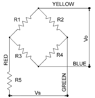
Each channel of all Biometrics Ltd Goniometers and Torsiometers consist electrically of a Full Wheatstone Bridge arrangement. The passive half of the bridges are housed within the sensors fixed plastic endblock. This is electrically screened to aid signal to noise ratio. With all twin axis sensors the two bridges have one common. Referring to the table below note the difference in bridge input and output impedance. To prolong battery life the sensors may be energised with as little as +1.0 Vdc, though 1.5 to 2.0 Vdc is preferable.
Use of Cable Type No. A1500
Push the black socket of the interconnect cable onto the mating black plug of the goniometer, ensuring that the polarisation marks are aligned before insertion. The plug and socket are self latching and should NOT be separated by pulling on either cable. To separate hold the plastic body of the plug and socket in each hand and pull.
The free end of the interconnect cable has 4 coloured PVC coated conductors and a screen braid.
- RED: +ve supply
- GREEN: supply ground or common
- YELLOW: +ve output differential volts
- BLUE: -ve output differential volts
For all goniometers the maximum permissible d.c. supply voltage is 5.0 volts. Current 4mA / supply volt nominal.
Goniometer sensitivity: 10µv/degree angle/supply volt. If a goniometer is energised with 5 volts d.c. and bent through an angle of 100°, the differential output will be 0.005 volts.
When used with instrumentation systems not supplied by Biometrics Ltd, no guarantee of unit performance can be given.
WARNING: THE USER SHOULD INSURE THAT WHATEVER SYSTEM THE GONIOMETER IS CONNECTED TO COMPLIES WITH ALL RELEVANT MEDICAL AND/OR ELECTRICAL SAFETY STANDARDS. IN PARTICULAR, ANY RESULTING MEDICAL SYSTEM MUST COMPLY TO EUROPEAN MEDICAL ELECTRICAL SAFETY STANDARD EN60601-1 1990.

Vo: Output Voltage(differential), Vs: Supplied Voltage
Referring to the above schematic the following table shows the resistor values for the various sensor types.
| Type No. | Resistor Values |
||
| R1 / R2 | R3 / R4 | R5 | |
| F35 | 67 | 11300 | 80 |
| SG65 | 115 | 11300 | 20 |
| SG75 | 110 | 11300 | 17 |
| SG110 | 60 | 11300 | 145 |
| SG150 | 80 | 11300 | 120 |
All values in ohms. Tolerance ± 10%.


